
TM 5-2420-231-23-3
0287
RIGHT TOWER BOOT REMOVAL CONTINUED
NOTE
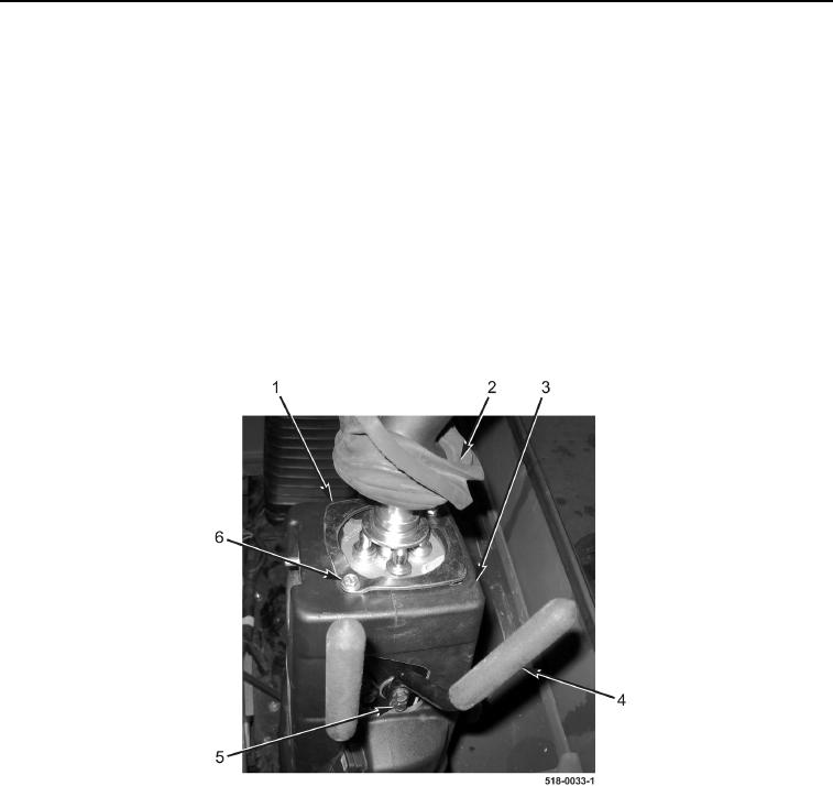
Note location of bolts and retainer plate to aid in installation.
3. Remove two bolts (Figure 6, Item 6) and retainer plate (Figure 6, Item 1) from right backhoe control tower
(Figure 6, Item 3).
NOTE
Note position and orientation of backhoe control tower tilt release handles to aid in
installation.
4. Remove four bolts (Figure 6, Item 5) and two backhoe control tower tilt release handles (Figure 6, Item 4) from
right backhoe control tower (Figure 6, Item 3).
5. Lower joystick boot (Figure 6, Item 2).
Figure 6. Tilt Release Handles.
0287