
TM 5-2420-231-23-3
0287
LEFT TOWER BOOT REMOVAL CONTINUED
NOTE
Note location of bolts and retainer plate to aid in installation.
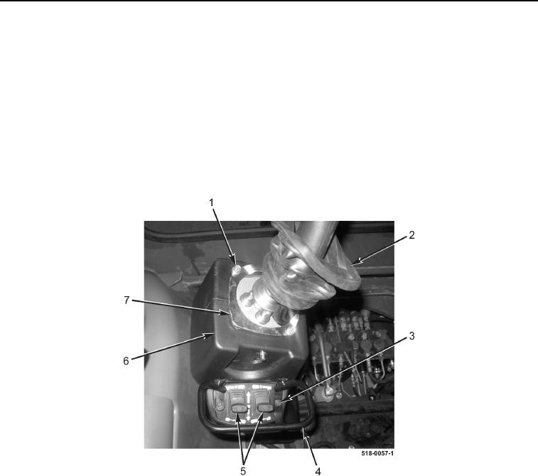
4. Remove two bolts (Figure 3, Item 1) and retainer plate (Figure 3, Item 7) from left backhoe control tower
(Figure 3, Item 6).
5. Remove two bolts (Figure 3, Item 3) and switch guard (Figure 3, Item 4) from left backhoe control tower
(Figure 3, Item 6).
6. Remove stabilizer switches (Figure 3, Item 5) from left backhoe control tower (Figure 3, Item 6).
7. Lower joystick boot (Figure 3, Item 2).
Figure 3. Retainer Plate.
0287