
TM 5-2420-231-23-3
0287
LEFT TOWER BOOT REMOVAL CONTINUED
NOTE
Tag and mark wires to aid in installation.
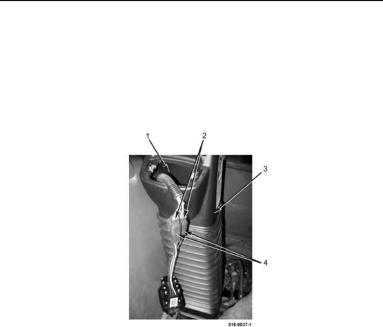
8. Disconnect two wiring harness connectors (Figure 4, Item 2) from stabilizer switches (Figure 4, Item 4).
9. Remove stabilizer switches (Figure 4, Item 4) from machine.
10. Tuck wiring harness connectors (Figure 4, Item 2) down into left backhoe control tower boot opening
(Figure 4, Item 1).
11. Remove left backhoe control tower boot (Figure 4, Item 3) from machine.
Figure 4. Boot.
0287
END OF TASK