
TM 5-2420-231-23-3
0287
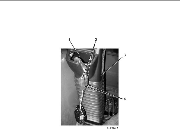
LEFT TOWER BOOT INSTALLATION
0287
1. Install left backhoe control tower boot (Figure 12, Item 3) on machine.
2. Pull wiring harness connectors (Figure 12, Item 2) up through left backhoe control tower boot opening
(Figure 12, Item 1).
3. Connect two wiring harness connectors (Figure 12, Item 2) to stabilizer switches (Figure 12, Item 4).
Figure 12. Boot.
0287