
TM 5-2420-231-23-3
0291
INSTALLATION CONTINUED
NOTE
The procedure for swing cylinder pin removal and replacement is identical for left-hand
and right-hand swing cylinder pin. Left-hand swing cylinder is shown in this procedure.
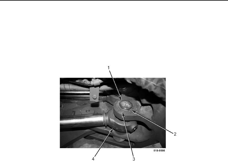
6. Lightly grease and install pin (Figure 11, Item 1), two washers (Figure 11, Item 3), and retaining rings
(Figure 11, Item 2) on swing cylinder (Figure 11, Item 4).
7. Repeat step 6 for right-hand side.
Figure 11. Swing Cylinder Pivot Pin.
0291