
TM 5-2420-231-23-3
0295
REMOVAL CONTINUED
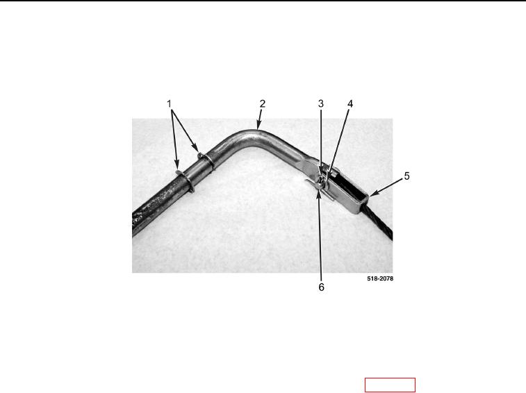
8. Remove cotter pin (Figure 6, Item 3), washer (Figure 6, Item 4), clevis pin (Figure 6, Item 6), and cable/clevis
assembly (Figure 6, Item 5) from rod (Figure 6, Item 2). Discard cotter pin.
9. Remove two clips (Figure 6, Item 1) from rod (Figure 6, Item 2).
Figure 6. Clevis.
0295
END OF TASK
CLEANING AND INSPECTION
0295
Clean and inspect all parts IAW Mechanical General Maintenance Instructions (WP 0369).
END OF TASK
INSTALLATION
0295
1. Install two clips (Figure 6, Item 1) from rod (Figure 6, Item 2).
2. Install cable/clevis assembly (Figure 6, Item 5), clevis pin (Figure 6, Item 6), washer (Figure 6, Item 4), and
new cotter pin (Figure 6, Item 3) on rod (Figure 6, Item 2).