
TM 5-2420-231-23-3
0301
INSTALLATION CONTINUED
6. Install two washers (Figure 16, Item 1) and bolts (Figure 16, Item 2) on hydraulic oil tank (Figure 16, Item 3).
7. Remove lifting device from battery box and hydraulic oil tank.
Figure 16. Hydraulic Oil Tank Bolts at Rear of Battery Box.
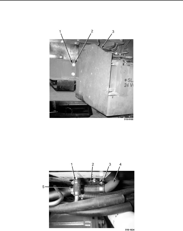
0301
8. Tighten clamp (Figure 17, Item 1) on return hose (Figure 17, Item 5) and hydraulic oil tank (Figure 17, Item 4).
9. Install supply hose (Figure 17, Item 2) on machine.
10. Connect supply hose (Figure 17, Item 2) and tighten clamp (Figure 17, Item 3) on hydraulic oil tank
(Figure 17, Item 4).
Figure 17. Hoses.
0301