
TM 5-2420-231-23-3
0327
INSTALLATION CONTINUED
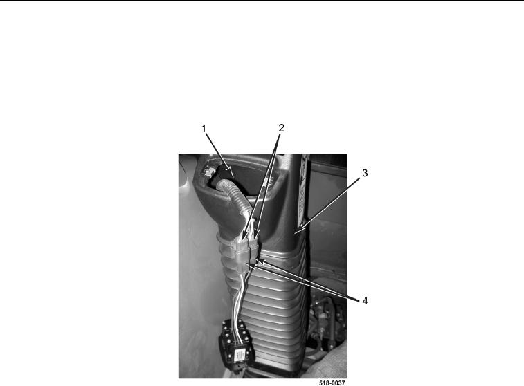
64. Install left backhoe control tower boot (Figure 72, Item 3) on machine.
65. Route harness connectors (Figure 72, Item 2) up through left backhoe control tower boot opening
(Figure 72, Item 1).
66. Connect two harness connectors (Figure 72, Item 2) to stabilizer switch harness connectors
(Figure 72, Item 4).
Figure 72. Left Backhoe Control Tower Boot.
0327