
TM 5-2420-231-23-3
0327
INSTALLATION CONTINUED
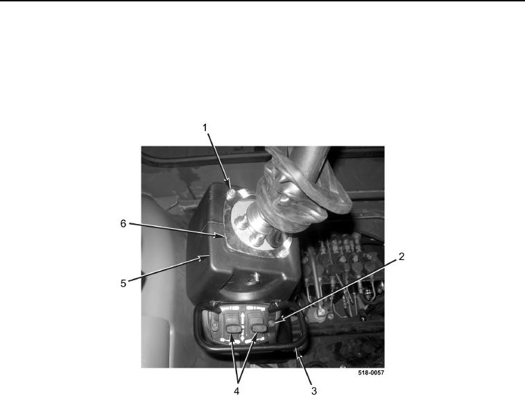
67. Install stabilizer switches (Figure 73, Item 4) on left backhoe control tower (Figure 73, Item 5).
68. Install switch guard (Figure 73, Item 3) and two bolts (Figure 73, Item 2) on left backhoe control tower
(Figure 73, Item 5).
69. Install retainer plate (Figure 73, Item 6) and two bolts (Figure 73, Item 1) on left backhoe control tower
(Figure 73, Item 5).
Figure 73. Stabilizer Switches.
0327