
4
TM 5-2420-231-23-3
FIELD MAINTENANCE
-
CAB HEATER CONTROL VALVE REPLACEMENT
0
355
Removal, Cleaning and Inspection, Installation
INITIAL SETUP
Equipment Conditions
Tools and Special Tools
Tool Kit, General Mechanic's
Engine coolant drained (WP 0090)
0
0
(WP 0376, Item 117)
Instrument panel right-side cover removed
0
(WP 0176)
Materials/Parts
Estimated Time to Complete
Rag, Wiping (WP 0375, Item 25)
0
4.5 hr
References
0
0
WP 0374 (Group Number 0841)
0
REMOVAL
0355
NOTE
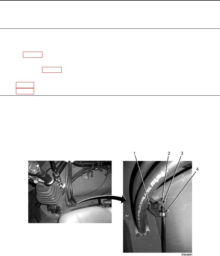
Note position of cable and retaining clip prior to disassembly.
1. Remove retaining clip (Figure 1, Item 4) from heater control valve (Figure 1, Item 1).
2. Disconnect cable (Figure 1, Item 3) from heater control valve lever (Figure 1, Item 2).
Figure 1. Heater Control Valve Connection.
0355