
TM 5-2420-231-23-3
0354
INSTALLATION CONTINUED
WARNING
Use caution when using adhesives and sealants. Prolonged inhalation of vapors can
cause lung irritation. Contact with skin can cause dermatitis. Wear gloves and safety
goggles and use product in a well-ventilated area away from open flame. If ingested, keep
individual calm and seek medical attention. DO NOT induce vomiting. If contact with skin
or eyes is made, flush thoroughly with water. Dispose of cleanup rags IAW local policy and
ordinances. Failure to follow this warning may result in injury to personnel.
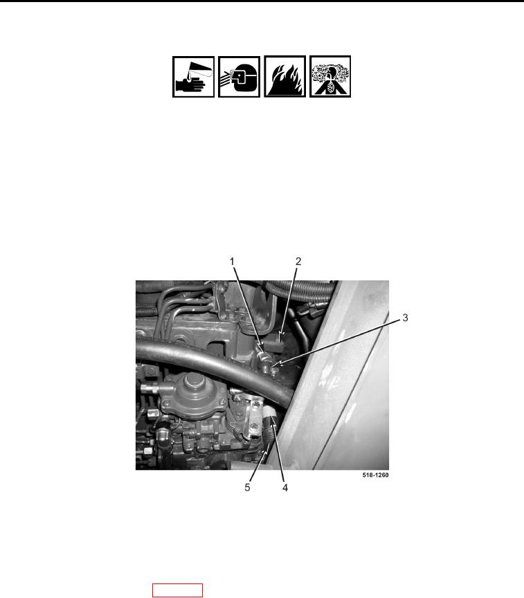
16. Apply sealing compound to fitting (Figure 13, Item 3) and install fitting on cylinder head (Figure 13, Item 2).
17. Install tubing (Figure 13, Item 5) on left-side heater hose (Figure 13, Item 4).
18. Connect left-side heater hose (Figure 13, Item 4) to fitting (Figure 13, Item 3).
19. Tighten clamp (Figure 13, Item 1) on left-side heater hose (Figure 13, Item 4).
Figure 13. Left-Side Heater Hose.
0354
END OF TASK
FOLLOW-ON TASKS
0354
1. Install instrument panel right-side cover (WP 0176).
2. Install front floor cover plate (WP 0306).
3. Install air cleaner barrier curtain (WP 0099).
4. Fill engine coolant (WP 0090).
END OF TASK
END OF WORK PACKAGE
0354-11/(12 blank)