
TM 5-2420-231-23-3
0361
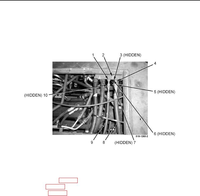
INSTALLATION CONTINUED
11. Install spacer (Figure 10, Item 3), clamp (Figure 10, Item 6), bolt (Figure 10, Item 7), and nut (Figure 10, Item
2) on A/C tubes (Figure 10, Items 1 and 4).
12. Install new O-ring (Figure 10, Item 5) on A/C tube (Figure 10, Item 4) and connect A/C tube to A/C hose
(Figure 10, Item 8).
13. Install new O-ring (Figure 10, Item 10) on A/C tube (Figure 10, Item 1) and connect A/C tube to A/C hose
(Figure 10, Item 9).
Figure 10. Floor Connection.
0361
END OF TASK
FOLLOW-ON TASKS
0361
1. Install right-side blower duct (WP 0350).
2. Install cab floor plate (WP 0306).
3. Recharge A/C system (WP 0364).
END OF TASK
END OF WORK PACKAGE
0361-9/(10 blank)