
TM 5-3805-255-14
0022
REMOVAL CONTINUED
NOTE
Relieve brake air pressure by pressing brake pedal until air pressure gauge reads
zero psi.
8. Disconnect air compressor outlet line. Disconnect air compressor governor line at air compressor (WP 0063
and WP 0064).
9. Remove U-bolt and disconnect oil drain hose from fuel tank.
NOTE
Place a suitable drain pan under fuel line connections at fuel tank.
10. Disconnect fuel lines from fuel tank (WP 0031).
11. Disconnect accelerator cable from injector actuating arm (WP 0028).
12. Disconnect emergency shutdown control linkage from fuel injection pump (WP 0028).
13. Remove two electrical wires from oil pressure sending unit (WP 0044).
14. Remove electrical wire from coolant temperature sending unit (WP 0044).
NOTE
Place a suitable drain pan under heater hose shut off valves.
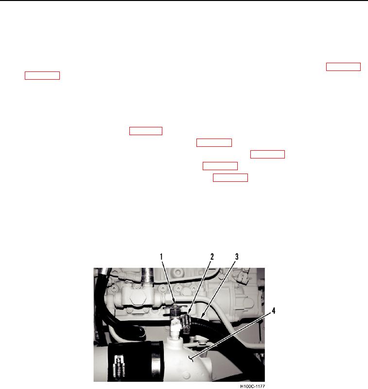
15. Close heater hose shut-off valves (Figure 2, Item 1).
16. Remove two clamps (Figure 2, Item 2) and heater hoses (Figure 2, Item 3) from engine (Figure 2, Item 4).
Figure 2. Heater Hoses.
022
0022-3