• Home
  • Download PDF
  • Order CD-ROM
  • Order in Print
SWITCH REPLACEMENT
Figure 3. ON/OFF Switch.

Maintenance Manual For Loader, Scoop Type, Ded 4 X 4, Articulated Frame Steer, 4.5 To 5 Cu. Yd.
Page Navigation
  396    397    398    399    400  401  402    403    404    405    406  
img
TM 5-3805-255-14
0042
REMOVAL CONTINUED
ON/OFF Switch
00042
NOTE
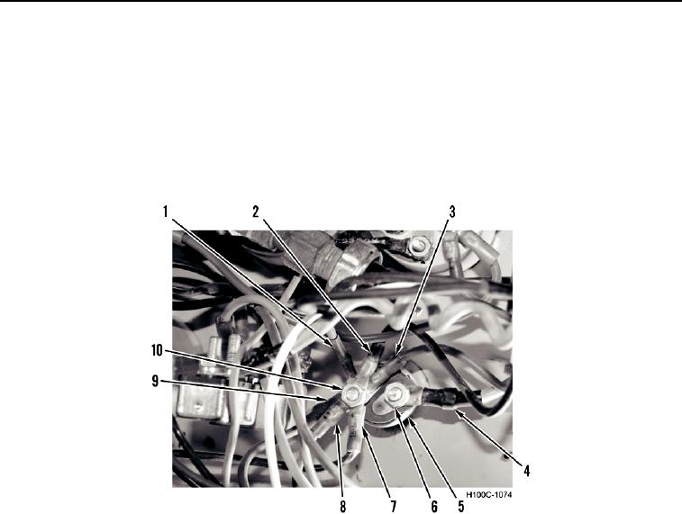
Tag and identify all wires for ease of installation.
1. Remove nut (Figure 2, Item 10) and six wires (Figure 2, Items 1, 2, 3, 7, 8, and 9) from ON/OFF switch
(Figure 2, Item 5).
2. Remove nut (Figure 2, Item 6) and wire (Figure 2, Item 4) from ON/OFF switch (Figure 2, Item 5).
Figure 2. ON/OFF Switch Wiring.
0042
0042-2


Privacy Statement
Press Release
Contact

© Copyright Integrated Publishing, Inc.. All Rights Reserved.