
TM 5-3805-255-14
0042
REMOVAL CONTINUED
Starter Button -- Continued
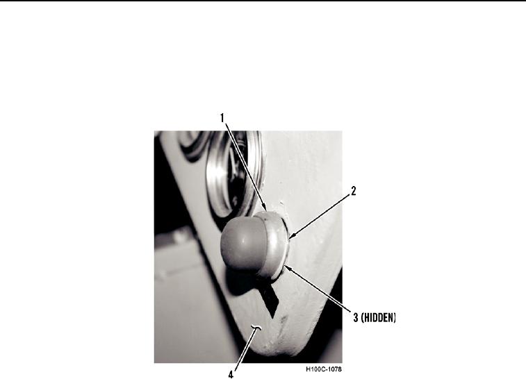
4. Remove starter button (Figure 7, Item 1) and lockwasher (Figure 7, Item 2) from dash panel (Figure 7, Item 4).
Discard lockwasher.
5. Remove starter button switch (Figure 7, Item 3) from rear of dash panel (Figure 7, Item 4).
Figure 7. Starter Button.
0042
END OF TASK
INSTALLATION
00042
Starter Button
00042
1. Install starter button switch (Figure 7, Item 3) in rear of dash panel (Figure 7, Item 4).
2. Install new lockwasher (Figure 7, Item 2) and starter button (Figure 7, Item 1) on dash panel (Figure 7, Item 4).
3. Tighten locknut (Figure 6, Item 1) on starter button switch (Figure 6, Item 7).
NOTE
Install wires as noted during removal.
4. Install wire (Figure 6, Item 2) and nut (Figure 6, Item 6) on starter button switch (Figure 6, Item 7).
5. Install wire (Figure 6, Item 4) and nut (Figure 6, Item 3) on starter button switch (Figure 6, Item 7).
0042-7