
TM 5-3805-255-14
0042
INSTALLATION CONTINUED
ON/OFF Switch -- Continued
NOTE
Install wires as noted during removal.
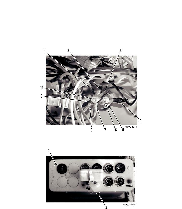
3. Install wire (Figure 11, Item 4), and nut (Figure 11, Item 6) on ON/OFF switch (Figure 11, Item 5).
4. Install six wires (Figure 11, Items 1, 2, 3, 7, 8, and 9) and nut (Figure 11, Item 10) on ON/OFF switch (Figure
11, Item 5).
Figure 11. ON/OFF Switch Wiring.
0042
5. Install gauge panel (Figure 12, Item 1) on instrument panel (Figure 12, Item 2).
Figure 12. Gauge Cluster.
0042
END OF TASK
END OF WORK PACKAGE
0042-11/(12 blank)