
4
TM 5-3805-255-14
FIELD MAINTENANCE
-
ELECTRIC GAUGE REPLACEMENT
0
043
Removal, Cleaning and Inspection, Installation
INITIAL SETUP
References
Tools and Special Tools
0
0
Tool Kit, General Mechanic's, Automotive (WP
0
0128, Item 20)
0
Equipment Condition
0
Materials/Parts
Machine parked on level ground (WP 0005)
0
0
Rag, Wiping (WP 0130, Item 28)
Parking brake applied (WP 0005)
0
0
Tag, Marker (WP 0130, Item 37)
Engine OFF (WP 0005)
0
0
Battery disconnect switch in OFF position
0
REMOVAL
00043
NOTE
The following procedure is for the fuel gauge. All other electrical gauges are removed in a
similar manner.
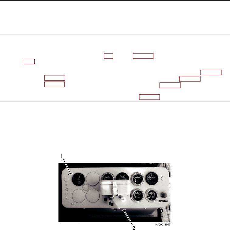
1. Remove gauge face plate (Figure 1, Item 1) from instrument panel (Figure 1, Item 2).
Figure 1. Gauge Cluster.
0043
0043-1