
TM 5-3805-255-14
0048
REMOVAL CONTINUED
NOTE
Tag and identify all hose flanges for ease of installation. Cap all hoses to prevent
contamination and leaks.
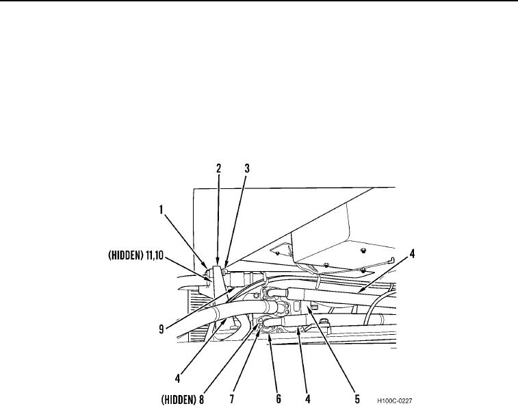
2. Remove 12 bolts (Figure 2, Item 7), six split flanges (Figure 2, Item 6), three hoses (Figure 2, Item 4), and
O-rings (Figure 2, Item 8) from demand valve (Figure 2, Item 5). Discard O-rings.
3. Remove four bolts (Figure 2, Item 3), nuts (Figure 2, Item 1), split flanges (Figure 2, Item 10), two hoses
(Figure 2, Item 9), and O-rings (Figure 2, Item 11) from hose bracket (Figure 2, Item 2). Discard O-rings.
Figure 2. Demand Valve Hoses.
0048
0048-3