
TM 5-3805-255-14
0048
INSTALLATION CONTINUED
NOTE
Some propeller shafts have bolts threaded into universal joint caps.
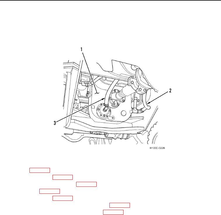
10. Install strainer hose (Figure 8, Item 3) and sump hose (Figure 8, Item 2) on transmission (Figure 8, Item 1).
Figure 8. Rear Axle Propeller Shaft.
0048
11. Install cab (WP 0075).
12. Install propeller shafts (WP 0049).
13. Install transmission control linkage (WP 0046).
14. Stow safety bar (WP 0005).
15. Fill hydraulic reservoir (WP 0018).
16. Add required fluid to transmission-converter system (WP 0018).
17. Start engine, check controls for proper operation (WP 0005).
END OF TASK
END OF WORK PACKAGE
0048-8