
TM 5-3805-255-14
0048
INSTALLATION CONTINUED
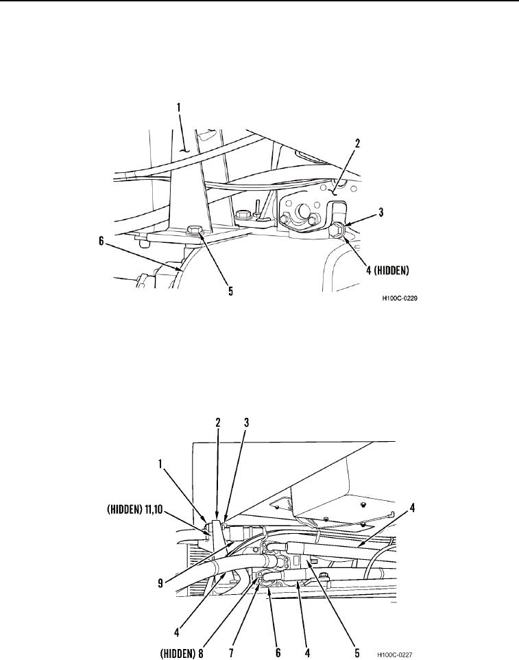
6. Install hose bracket (Figure 6, Item 1) and two bolts (Figure 6, Item 5) on transmission (Figure 6, Item 6).
7. Install demand valve (Figure 6, Item 2), three bolts (Figure 6, Item 3), and nuts (Figure 6, Item 4) on
transmission (Figure 6, Item 6).
Figure 6. Hose Bracket and Demand Valve.
0048
8. Install three new O-rings (Figure 7, Item 8), hoses (Figure 7, Item 4), six split flanges (Figure 7, Item 6), and 12
machine bolts (Figure 7, Item 7) on demand valve (Figure 7, Item 5).
9. Install two new O-rings (Figure 7, Item 11), hoses (Figure 7, Item 9), four split flanges (Figure 7, Item 10), bolts
(Figure 7, Item 3), and nuts (Figure 7, Item 1) on hose bracket (Figure 7, Item 2).
Figure 7. Demand Valve Hoses and Bracket.
0048
0048-7