
TM 5-3805-255-14
0061
INSTALLATION
00061
Right Treadle Valve
00061
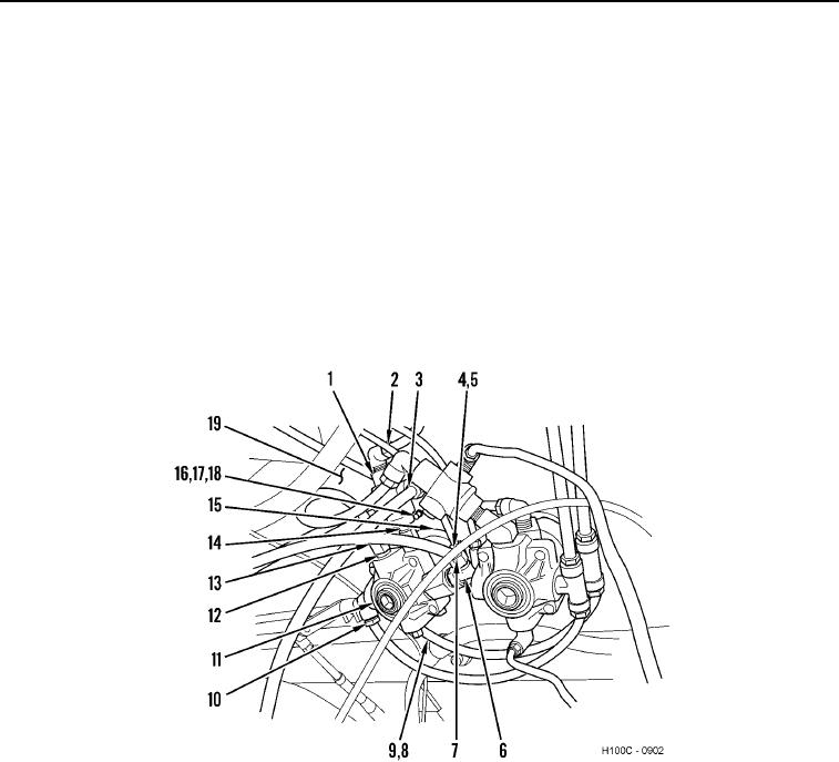
1. Install right treadle valve (Figure 17, Item 15), three bolts (Figure 17, Item 16), new lockwashers (Figure 17,
Item 18), and nuts (Figure 17, Item 17) on floorboard (Figure 17, Item 19).
2. Install fittings (Figure 17, Items 12 and 14) on right treadle valve (Figure 17, Item 15).
3. Install elbows (Figure 17, Items 5, 6, and 9) on right treadle valve (Figure 17, Item 15).
4. Install right check valve (Figure 17, Item 1) on fitting (Figure 17, Item 14).
5. Connect tube (Figure 17, Item 13) to fitting (Figure 17, Item 12).
6. Connect hose (Figure 17, Item 7) to elbow (Figure 17, Item 6).
7. Connect hoses (Figure 17, Items 8 and 10) to elbows (Figure 17, Items 9 and 11).
8. Connect tube (Figure 17, Item 4) to elbow (Figure 17, Item 5).
9. Connect hoses (Figure 17, Items 2 and 3) to right check valve (Figure 17, Item 1).
Figure 17. Right Treadle Valve.
0061
0061-14