TM 5-3805-255-14
0061
INSTALLATION CONTINUED
NOTE
Align marks on section and body during assembly.
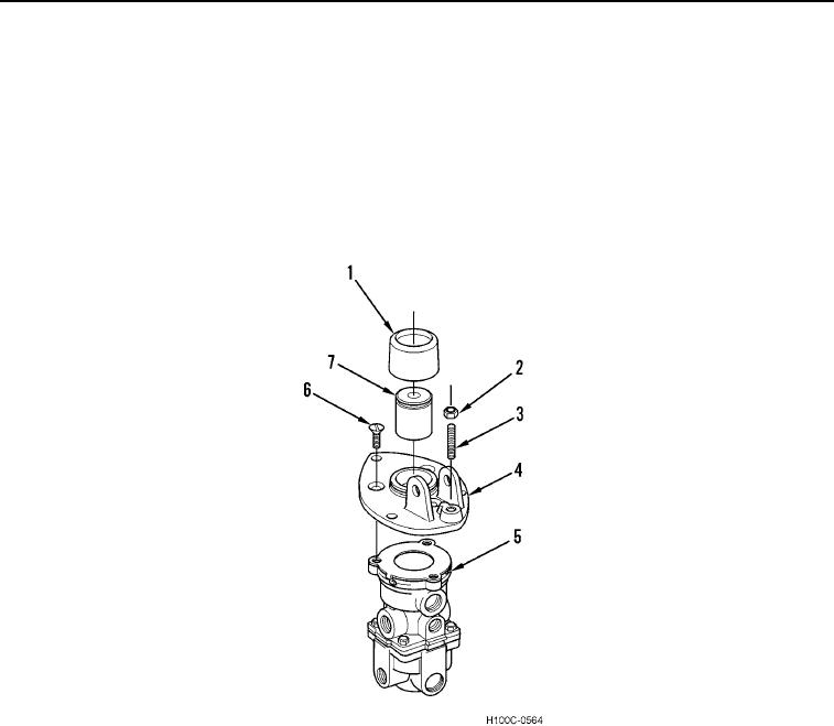
10. Install mounting plate (Figure 18, Item 4) and three screws (Figure 18, Item 6) on body (Figure 18, Item 5).
11. Install plunger (Figure 18, Item 7) on mounting plate (Figure 18, Item 4).
12. Install set screw (Figure 18, Item 3) and stop nut (Figure 18, Item 2) on mounting plate (Figure 18, Item 4).
13. Install rubber boot (Figure 18, Item 1) on plunger (Figure 18, Item 7) and mounting plate (Figure 18, Item 4).
Figure 18. Plunger.
0061
0061-15

