
TM 5-3805-255-14
0064
DISASSEMBLY CONTINUED
CAUTION
Each connecting rod is matched to its own bearing cap. Do not interchange. Before
separating, mark each rod and cap for proper fit and ease of installation. Failure to follow
this caution may result in damage to equipment.
NOTE
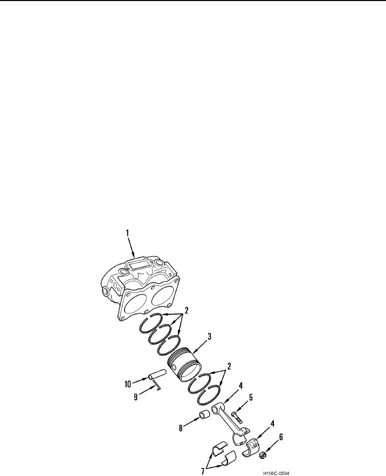
Disassembly of one piston is shown. Repeat steps 23 through 29 for other piston.
23. Remove two bolts (Figure 6, Item 5), washer key (Figure 6, Item 6), and bearing cap from connecting rod
(Figure 6, Item 4).
24. Remove piston (Figure 6, Item 3) and connecting rod (Figure 6, Item 4) from cylinder block (Figure 6, Item 1).
25. Replace bearing cap on connecting rod (Figure 6, Item 4).
26. Remove piston rings (Figure 6, Item 2) from piston (Figure 6, Item 3).
27. Remove wrist pin lock (Figure 6, Item 9) and press wrist pin (Figure 6, Item 10) from piston (Figure 6, Item 3)
and connecting rod (Figure 6, Item 4).
28. Remove bearing sleeve (Figure 6, Item 7) from bearing cap and connecting rod (Figure 6, Item 4).
29. Remove wrist pin bushing (Figure 6, Item 8) from connecting rod (Figure 6, Item 4).
Figure 6. Piston.
0064
0064-8