
TM 5-3805-255-14
0064
ASSEMBLY CONTINUED
NOTE
Procedure describes one cylinder assembly; repeat for other cylinder.
Lubricate pistons, piston bores, piston rings, wrist pin bushings, and connecting rod
bearings with clean oil prior to assembly.
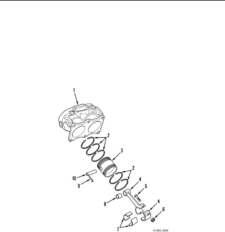
7. Align oil hole in wrist pin bushing with oil hole in connecting rod. Press wrist pin bushing (Figure 14, Item 8) in
connecting rod (Figure 14, Item 4).
8. Install sleeves (Figure 14, Item 7) in bearing cap and connecting rod (Figure 14, Item 4).
9. Position connecting rod (Figure 14, Item 4) in piston (Figure 14, Item 3) and press wrist pin (Figure 14, Item 10)
into piston (Figure 14, Item 3) with lock holes in pin aligned with lock holes in piston.
Figure 14. Piston.
0064
0064-15