TM 5-3805-255-14
0064
CLEANING AND INSPECTION CONTINUED
18. When pressing new bushings into place, be sure oil hole in bushing lines up with oil hole in connecting rod.
Bushings must then be reamed, honed, or bored to provide between 0.0001 in. (0.0025 mm) and 0.0006 in.
(0.0152 mm) clearance between bushing and wrist pin.
19. Inspect connecting rod bearings for proper fit on crankshaft journals. Check connecting rod bearings for wear.
If worn or cracked, replace rod bearings. Connecting rod caps are not interchangeable. Position caps so two
insert locking slots are adjacent to same capscrew.
20. Inspect crankshaft journals for out-of-round, and replace if necessary.
21. Inspect oil seal ring grooves for wear, and replace crankshaft if necessary.
END OF TASK
ASSEMBLY
00064
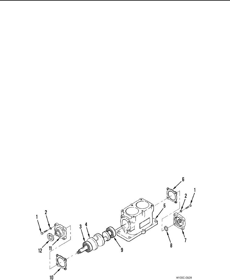
1. Press ball bearings (Figure 13, Items 3 and 9) onto crankshaft.
2. Position crankshaft (Figure 13, Item 4) and ball bearings (Figure 13, Items 3 and 9) into crankcase (Figure 13,
Item 5), making sure drive end of crankshaft is positioned as marked during removal. Front bearing (Figure 13,
Item 3) should bottom against front cover (Figure 13, Item 11).
3. Press crankshaft (Figure 13, Item 4) and ball bearings (Figure 14, Items 3 and 9) in crankcase (Figure 13,
Item 5).
4. Install new oil seal ring (Figure 13, Item 8) on rear cover (Figure 13, Item 7). Install new gasket (Figure 13,
Item 6), rear cover, four new lockwashers (Figure 13, Item 2), and bolts (Figure 13, Item 1) on crankcase
(Figure 13, Item 5). Note rear cover alignment marks.
5. Install new oil seal ring (Figure 13, Item 12) on front cover (Figure 13, Item 11).
6. Install new gasket (Figure 13, Item 10), front cover (Figure 13, Item 11), four new lockwashers (Figure 13,
Item 2), and bolts (Figure 13, Item 1) on crankcase (Figure 13, Item 5). Note front cover alignment marks.
Figure 13. Crankshaft.
0064
0064-14

