
TM 5-3805-255-14
0068
ADJUSTMENT CONTINUED
00068
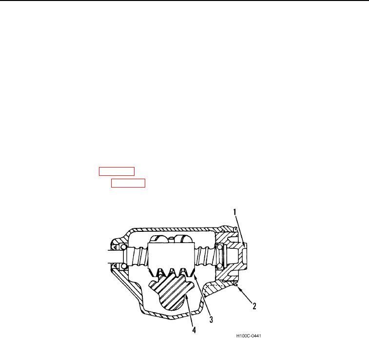
4. If indicated pull does not lie between given limits, make the following adjustments:
a. Loosen locknut (Figure 5, Item 2).
b. Turn adjuster (Figure 5, Item 1) until required resistance to pull (1.5 to 5.5 lb-in. [0.169 to 0.621 Nm)] is
reached.
c.
Tighten locknut (Figure 5, Item 2) to 18 to 27 lb-ft (24 to 37 Nm) torque and recheck pull. Pull resistance
must lie between limits specified after locknut is tightened.
d. Turn lash adjuster screw (Figure 5, Item 1) clockwise to remove lash from ball nut (Figure 5, Item 4) gear
teeth and pitman shaft (Figure 5, Item 3) gear teeth. Tighten locknut (Figure 5, Item 2).
e. Check pull with socket and lb-in. torque wrench as before, taking highest reading of scare as shaft is
turned through center position. This should be 3.0 to 7.0 lb-in. (0.339 to 0.790 Nm) over bearing adjust-
ment but not to exceed a total of 11.0 lb-in. (1.24 Nm).
f.
Readjust lash adjuster screw (Figure 5, Item 1) if necessary to obtain proper pull. Tighten locknut (Figure
5, Item 2) to 18 to 27 lb-ft (24 to 37 Nm) torque and recheck pull. Pull resistance must lie between specified
limits after locknut is tightened.
5. Install body access panels (WP 0005).
6. Install drag link to pitman arm (WP 0072).
Figure 5. Gear Lash Final Adjustment.
068
END OF TASK
END OF WORK PACKAGE
0068-4