
TM 5-3805-255-14
0070
REMOVAL
00070
NOTE
Tag and identify all hose flanges for ease of installation. Cap all hose flanges to prevent
contamination and leaks.
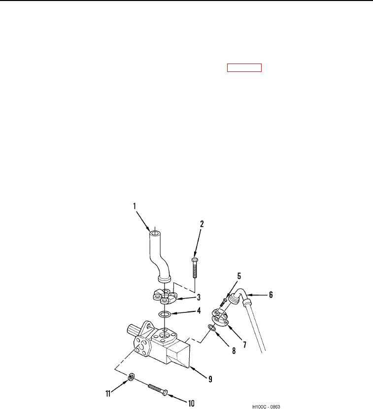
1. Remove hydraulic line (Figure 1, Item 1) from hydraulic reservoir (WP 0079).
2. Remove four bolts (Figure 1, Item 2), two split flanges (Figure 1, Item 3), hydraulic line (Figure 1, Item 1) and
O-ring (Figure 1, Item 4) from steering pump (Figure 1, Item 9). Discard O-ring.
3. Remove four bolts (Figure 1, Item 5), two split flanges (Figure 1, Item 7), hydraulic line (Figure 1, Item 6) and
O-ring (Figure 1, Item 8) from steering pump (Figure 1, Item 9). Discard O-ring.
4. Remove two bolts (Figure 1, Item 10) and lockwashers (Figure 1, Item 11) from steering pump (Figure 1, Item
9). Discard lockwashers.
CAUTION
Ensure splined shafts are not damaged when removing from converter. Failure to follow
this caution may result in damage to equipment.
5. Remove steering pump (Figure 1, Item 9) from converter.
Figure 1. Steering Pump.
0070
END OF TASK
0070-2