TM 5-3805-255-14
0069
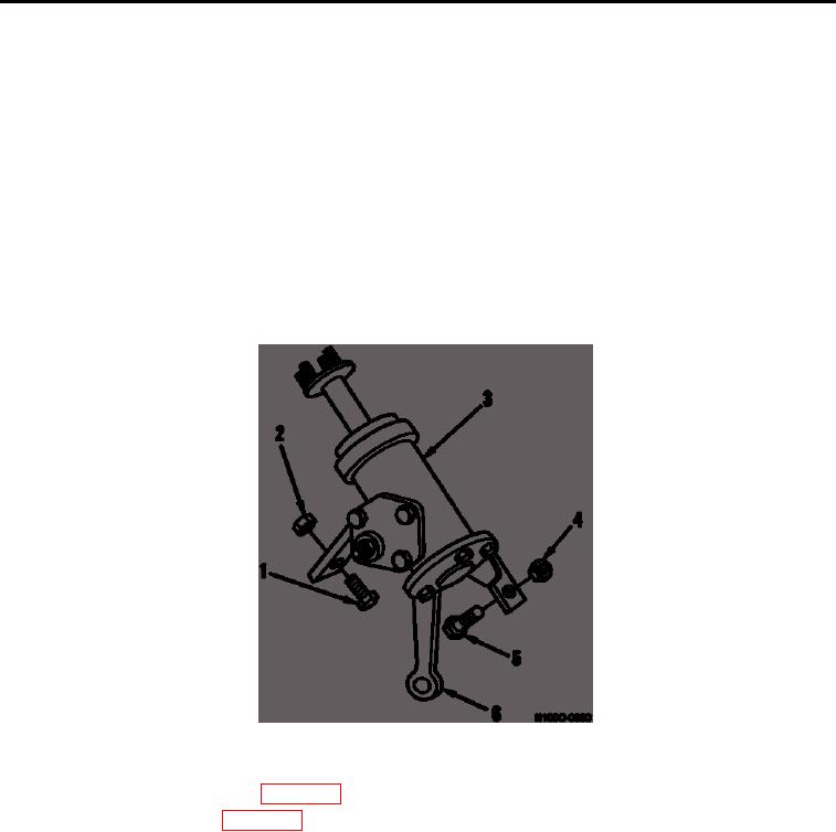
2. Adjust lock stop bolt (Figure 7, Item 1) until snug against pitman arm (Figure 7, Item 6) on steering gear
(Figure 7, Item 3).
3. Tighten nut (Figure 7, Item 2) to lock stop bolt (Figure 7, Item 1).
WARNING
Keep personnel clear of articulation area when moving. Failure to follow this warning may
result in injury or death to personnel.
4. Remove frame locking safety pin. Start engine and turn loader to left. Install frame locking safety pin. Turn
engine off.
5. Adjust stop bolt (Figure 7, Item 5) until snug against pitman arm (Figure 7, Item 6) on steering gear (Figure 7,
Item 3).
6. Tighten nut (Figure 7, Item 4) to lock stop bolt (Figure 7, Item 5).
Steering Gear Lock Stop Bolt.
Figure 7.
7. Remove safety bar from loader (WP 0005).
8. Install body access panels (WP 0005).
END OF TASK
END OF WORK PACKAGE
0069-10

