
TM 5-3805-255-14
0073
INSTALLATION
00073
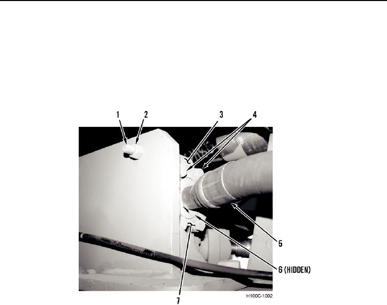
1. Install demand valve (Figure 5, Item 6), two bolts (Figure 5, Item 1), and nuts (Figure 5, Item 6) on frame.
NOTE
Connect previously tagged lines to their proper ports as identified on removal. Use new
O-rings at all split flange connections. Be sure all connections are tight and leak-free.
2. Install new O-ring (Figure 5, Item 6), hydraulic line (Figure 5, Item 5), two split flanges (Figure 5, Item 7), and
four machine bolts (Figure 5, Item 4) on demand valve.
Figure 5. Demand Valve, Driver Side.
0073
0073-8