TM 5-3805-255-14
0074
CENTER HINGE ADJUSTMENT CONTINUED
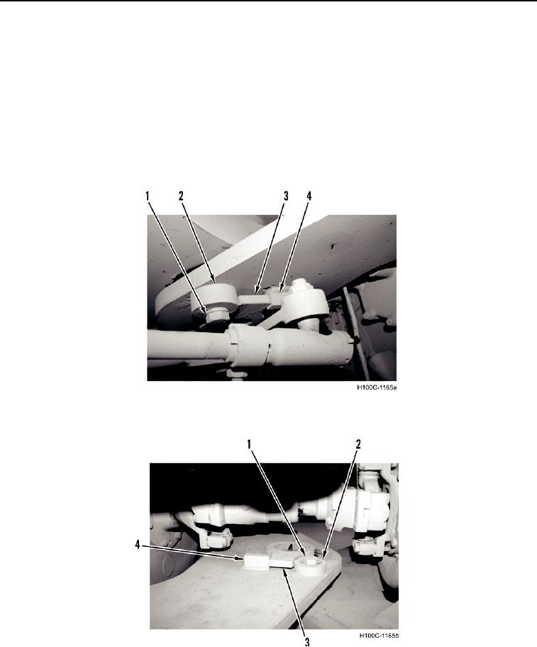
12. To adjust pin lock, bring pin lockplate (Figure 4 and Figure 5, Item 3) into contact with block (Figure 4 and
Figure 5, Item 4).
13. Rotate cam (Figure 4 and Figure 5, Item 2) clockwise to contact pin lockplate (Figure 4 and Figure 5, Item 3).
14. Tighten cam capscrew (Figure 4 and Figure 5, Item 1).
15. Repeat steps 11 through 13 for other hinge.
16. Position a dial indicator with its base on front frame and indicator needle on rear frame. Start engine and power
boom down until front tires clear the ground. Read and record indicator dial reading.
17. Raise boom to maximum height and read and record indicator dial reading. Total vertical movement shown by
dial indicator (difference between both readings) should not exceed 0.010 in. (0.254 mm).
18. If movement is excessive, repeat hinge adjustment procedure and re-check with dial indicator.
Figure 4. Upper Hinge Detail.
0074
Figure 5. Lower Hinge Detail.
0074
END OF TASK
END OF WORK PACKAGE
0074-4

