
4
TM 5-3805-255-14
FIELD MAINTENANCE
-
CENTER HINGE ADJUSTMENT
007
4
Locking Frame, Center Hinge Adjustment
INITIAL SETUP
References
Tools and Special Tools
0
0
Tool Kit, General Mechanic's, Automotive (WP
0
0128, Item 20)
0
Equipment Condition
Dial Indicator
0
0
Machine parked on level ground (WP 0005)
0
Materials/Parts
Parking brake applied (WP 0005)
0
0
Rag, Wiping (WP 0130, Item 28)
Engine OFF (WP 0005)
0
0
Battery disconnect switch in OFF position
0
LOCKING FRAME
00074
WARNING
Align frame halves and install safety bar with wheels in straight-ahead position. Failure to
install safety bar could lead to serious injury or death.
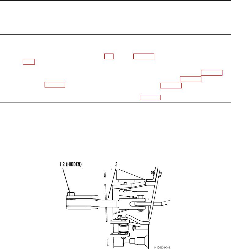
To lock loader halves in straight position, remove rear cotter pin (Figure 1, Item 2) and locking pin (Figure 1, Item
1), swing bar (Figure 1, Item 3) forward, and align with hole in forward section, and replace pins.
Figure 1. Safety Bar and Pin in Straight Lock Position.
0074
END OF TASK
0074-1