
TM 5-3805-255-14
0075
REMOVAL CONTINUED
NOTE
Tag and identify all air lines to aid in installation.
Note and identify routing of air lines prior to removal from loader to aid in installation.
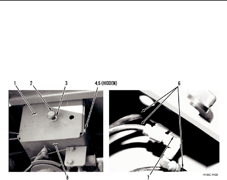
3. Remove four bolts (Figure 3, Item 4), lockwashers (Figure 3, Item 5), and cover (Figure 3, Item 1) from boom
stop control bracket (Figure 3, Item 8). Discard lockwashers.
4. Disconnect three air lines (Figure 3, Item 6) from wiper control valve (Figure 3, Item 7).
5. Remove knob (Figure 3, Item 2), nut (Figure 3, Item 3), and wiper control valve (Figure 3, Item 7) from cover
(Figure 3, Item 1).
Figure 3. Wiper Control Valve.
0075
0075-3