
TM 5-3805-255-14
0075
REMOVAL CONTINUED
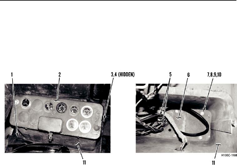
18. Remove two bolts (Figure 9, Item 3), lockwashers (Figure 9, Item 4), and control box cover (Figure 9, Item 2)
from control box (Figure 9, Item 11). Discard lockwashers.
19. Remove eight locknuts (Figure 9, Item 10), washers (Figure 9, Item 9), bolts (Figure 9, Item 7), and washers
(Figure 9, Item 8) from control box (Figure 9, Item 11) and connector plate (Figure 9, Item 6). Discard locknuts.
20. Disconnect two electrical connectors (Figure 9, Item 5) and feed connector plate (Figure 9, Item 6) through
hole in cab floor (Figure 9, Item 1).
21. Remove control box (Figure 9, Item 11) and control box cover (Figure 9, Item 2) from loader.
H100C-1106
Figure 9. Control Box and Cover.
0075
0075-8