
TM 5-3805-255-14
0075
INSTALLATION CONTINUED
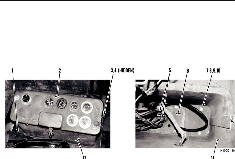
23. Install control box (Figure 25, Item 11) and control box cover (Figure 25, Item 2) on loader.
24. Feed connector plate (Figure 25, Item 6) through hole in cab floor (Figure 25, Item 1) and connect two
electrical connectors (Figure 25, Item 5).
25. Install eight washers (Figure 25, Item 8), bolts (Figure 25, Item 7), and new locknuts (Figure 25, Item 10) on
control box (Figure 25, Item 11) and connector plate (Figure 25, Item 6).
26. Install control box cover (Figure 25, Item 2), two new lockwashers (Figure 25, Item 4), and bolts (Figure 25,
Item 3) on control box (Figure 25, Item 11).
Figure 25. Control Box and Cover.
0075
0075-23