
TM 5-3805-255-14
0075
INSTALLATION CONTINUED
NOTE
Install and route all air lines as noted during removal.
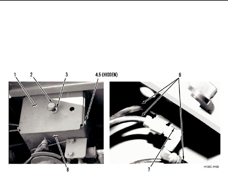
37. Install wiper control valve (Figure 31, Item 7), nut (Figure 31, Item 3), and knob (Figure 31, Item 2) on cover
(Figure 31, Item 1).
38. Connect three air lines (Figure 31, Item 6) to wiper control valve (Figure 31, Item 7).
39. Install cover (Figure 31, Item 1), four new lockwashers (Figure 31, Item 5), and bolts (Figure 31, Item 4) on
boom stop control bracket (Figure 31, Item 8).
Figure 31. Wiper Control Valve.
0075
0075-27