
TM 5-3805-255-14
0075
INSTALLATION CONTINUED
NOTE
Install and route all air lines as noted during removal.
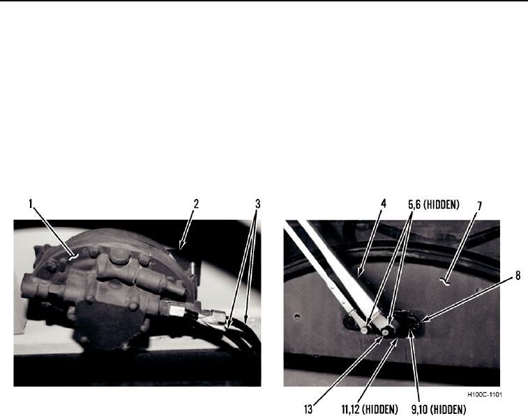
33. Install new gasket (Figure 30, Item 2), wiper motor (Figure 30, Item 1), spacer assembly (Figure 30, Item 8),
two washers (Figure 30, Item 10), and screws (Figure 30, Item 9) on front of cab (Figure 30, Item 7).
34. Install new lockwasher (Figure 30, Item 12) and nut (Figure 30, Item 11) on wiper motor shaft
(Figure 30, Item 13).
35. Connect two air lines (Figure 30, Item 3) to wiper motor (Figure 30, Item 1).
36. Install wiper arm assembly (Figure 30, Item 4), two washers (Figure 30, Item 6), and nuts (Figure 30, Item 5) on
cab (Figure 30, Item 7).
Figure 30. Wiper Motor and Arms.
0075
0075-26