
TM 5-3805-255-14
0075
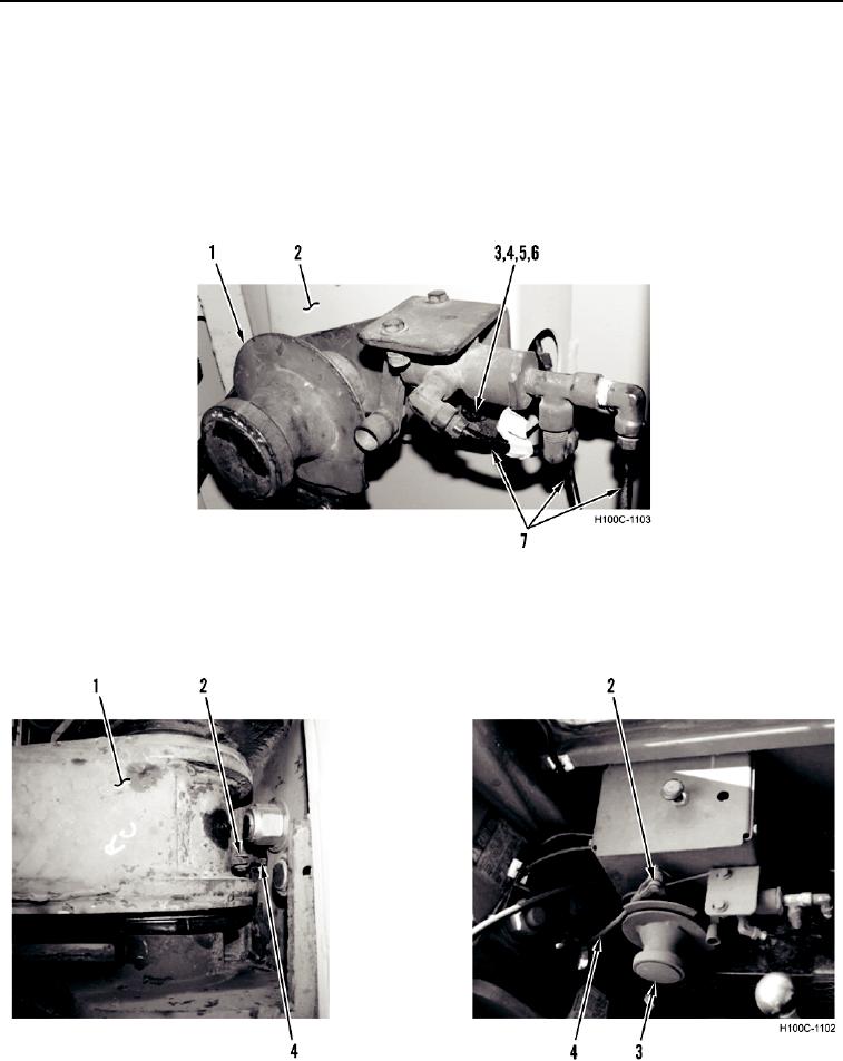
INSTALLATION CONTINUED
30. Install boom stop positioner control (Figure 28, Item 1), two washers (Figure 28, Item 3), new lockwashers
(Figure 28, Item 5), bolts (Figure 28, Item 4), and nuts (Figure 28, Item 6) on side wall of cab (Figure 28,
Item 2).
NOTE
Install and route air lines as noted during removal.
31. Connect three air lines (Figure 28, Item 7) to boom stop positioner control (Figure 28, Item 1).
Figure 28. Boom Stop Positioner Control.
0075
32. Install control rod (Figure 29, Item 4) and two pins (Figure 29, Item 2) on boom stop positioner control
(Figure 29, Item 3) and boom (Figure 29, Item 1).
H100C-1102
Figure 29. Control Rod.
0075
0075-25