
TM 5-3805-255-14
0081
INSTALLATION
0081
WARNING
Use extreme caution when handling heavy parts. Provide adequate support and use
assistance during procedure. Ensure that any lifting equipment is in good condition and of
suitable load capacity. Keep clear of heavy parts supported by lifting equipment. Failure to
follow this warning may result in injury or death to personnel.
1. Install bucket cylinder (Figure 3, Item 4) on loader. Install two weather seal clamps (Figure 3, Item 6) on each
end of cylinder.
2. Install two pins (Figure 3, Items 3 and 5), washers (Figure 3, Items 2 and 7), and bolts (Figure 3, Items 1 and 8)
on loader. Torque bolts to 170 lb-ft (230 Nm).
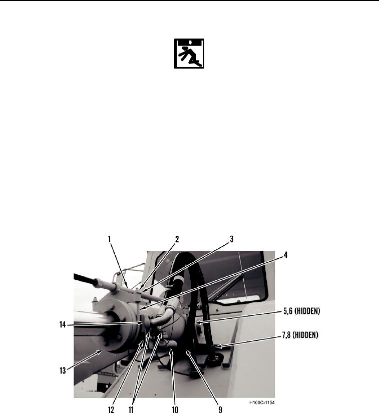
3. Install gauge tube (Figure 4, Item 1), two U-bolts (Figure 4, Item 4), four washers (Figure 4, Item 3), and nuts
(Figure 4, Item 2) on bucket cylinder (Figure 4, Item 13).
4. Install manifold pipe (Figure 4, Item 10) and four flange bolts (Figure 4, Item 9) on bucket cylinder (Figure 4,
Item 13).
5. Install two new O-rings (Figure 4, Items 6 and 8) in hydraulic lines (Figure 4, Items 5 and 7). Install two
separator plates (Figure 4, Item 12), hydraulic lines, four split-flange collars (Figure 4, Item 14), and eight
flange bolts (Figure 4, Item 11) on bucket cylinder (Figure 4, Item 13).
Figure 4. Hydraulic Lines.
0081
0081-5