
TM 5-3805-255-14
0080
ADJUSTMENT
00080
NOTE
Position both valve spools in their center positions.
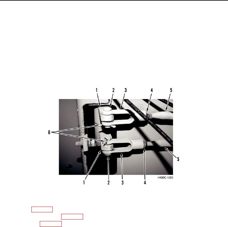
1. Loosen two jam nuts (Figure 9, Item 4) on clevises (Figure 9, Item 3) at threaded ends of control rods (Figure
9, Item 5).
2. With two control levers (Figure 9, Item 1) in vertical position, adjust clevises (Figure 9, Item 3) so control rod
(Figure 9, Item 5) bores align with bores of control levers.
3. Install clevis pins (Figure 9, Item 2) and new cotter pins (Figure 9, Item 6) on control rods (Figure 9, Item 5) and
control levers (Figure 9, Item 1).
4. Hold clevises (Figure 9, Item 3) in a horizontal position while tightening jam nuts (Figure 9, Item 4).
Figure 9. Hydraulic Control Linkage Adjustment.
0080
5. Start engine and after warm-up, operate hydraulic control levers through several cycles to check for proper
adjustment (WP 0005).
6. Install body access panels (WP 0005).
7. Stow safety bar (WP 0005).
END OF TASK
END OF WORK PACKAGE
0080-11/(12 blank)