
TM 5-3805-255-14
0081
REMOVAL CONTINUED
00081
3. Position suitable drain pan under cylinder to catch draining fluid.
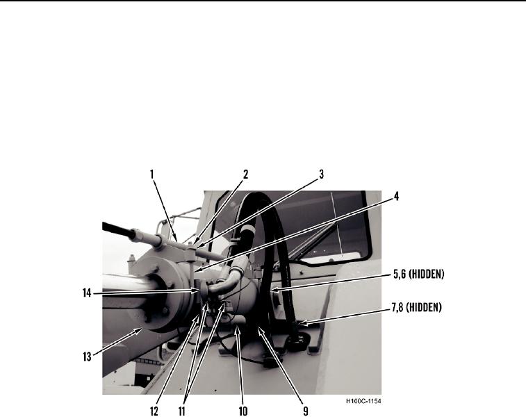
4. Remove eight flange bolts (Figure 2, Item 11), four split-flange collars (Figure 2, Item 14), two separator plates
(Figure 2, Item 12), and hydraulic lines (Figure 2, Items 5 and 7) from bucket cylinder (Figure 2, Item 13).
Remove two O-rings (Figure 2, Items 6 and 8) from lines. Drain cylinder. Discard O-rings.
5. Remove four flange bolts (Figure 2, Item 9) and manifold pipe (Figure 2, Item 10) from bucket cylinder (Figure
2, Item 13).
6. Remove four nuts (Figure 2, Item 2), washers (Figure 2, Item 3), two U-bolts (Figure 2, Item 4), and gauge tube
(Figure 2, Item 1) from bucket cylinder (Figure 2, Item 13).
Figure 2. Hydraulic Lines.
0081
0081-3