
TM 5-3805-255-14
0083
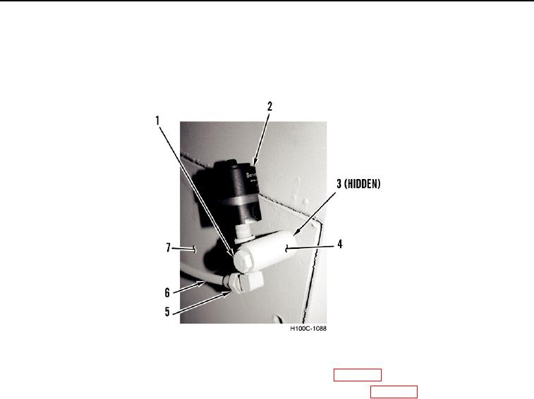
INSTALLATION CONTINUED
5. Install spacer (Figure 4, Item 4) and air filter indicator (Figure 4, Item 2) to battery box (Figure 4, Item 7).
6. Install bolt (Figure 4, Item 1) and nut (Figure 4, Item 3) to air filter indicator (Figure 4, Item 2).
7. Connect line (Figure 4, Item 6) to air filter indicator (Figure 4, Item 2). Tighten fitting (Figure 4, Item 5).
Figure 4. Air Filter Indicator.
0083
8. Fill hydraulic reservoir using oil filtered through a fine mesh screen (WP 0018).
9. Add oil through dipstick opening in reservoir and fill to full mark on dipstick (WP 0018).
10. Start and run engine to reduced speed while operating controls to circulate oil throughout various circuits and
to purge air from system.
11. Check reservoir oil level frequently, adding oil as necessary to full mark on dipstick.
12. Check all lines and fittings for leaks.
13. Stop engine and lower bucket to ground. Recheck oil level.
14. Tighten reservoir filler cap.
END OF TASK
END OF WORK PACKAGE
0083-5/(6 blank)