
TM 5-3805-255-14
0089
INSTALLATION CONTINUED
36. Install lubricating oil filter assembly (WP 0039).
37. Lubricate threads of fuel line nuts with lubricant. Connect fuel lines to injection pump and valve housings.
Torque nuts at pump to 30 lb-ft (40 Nm) and nuts at valve housings to 40 lb-ft (55 Nm).
38. Fill complete cooling system (WP 0018). Be certain that radiator and cylinder block drain valves are closed.
Also close vent valve on water manifold after venting system.
39. Check oil level in crankcase (WP 0018).
40. Adjust valve lash to cold setting as follows.
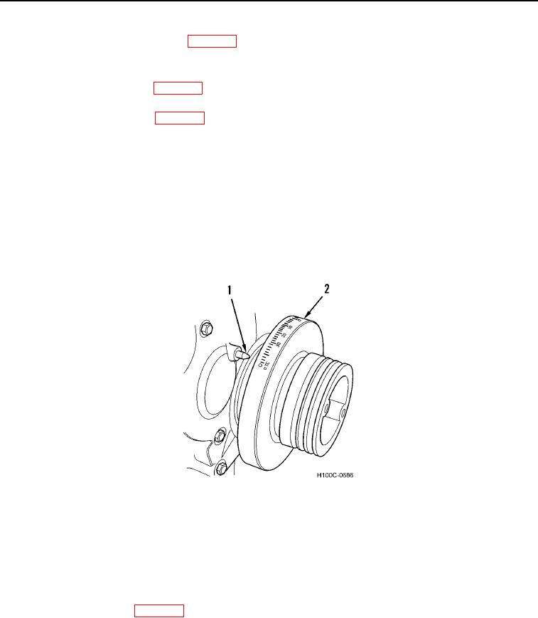
41. Pressure test valve housing-to-injection nozzle lines. Connect a test pump to injector nozzle pipe inlet elbow
outside of valve housing. Be sure engine timing pointer (Figure 33, Item 1) is set at "I-6" mark on vibration
damper (Figure 33, Item 2) for cylinder and injector to be tested.
42. Build up 3,000 psi. (20,685 kPa) pressure on test pump gauge and look for leaks at the following points:
a. Connector nut at housing fitting.
b. Fittings at each end of injector lines.
c.
Connector nut at injector nozzle inlet elbow.
Figure 33. Timing Mark.
0089
43. If leaks are found and further tightening does not stop leaks, replace defective parts.
44. Pressure test return lines. Connect test pump to return line tee or elbow. Apply 25 psi. (172 kPa) pressure and
look for leaks at all connector nuts and return lines.
45. If pressure cannot be maintained, look for leakage around injector nozzle fittings. Defective fittings must be
replaced.
46. Hand prime fuel system (WP 0018).
0089-33