TM 5-3805-255-14
0089
INSTALLATION CONTINUED
NOTE
Care must be taken when fitting nozzle supply tubes. Binding must not exist when lines
are tightened down. Supply tube lock nut must be left loose until fuel tubes are positioned
and connected to valve housing and then tighten down.
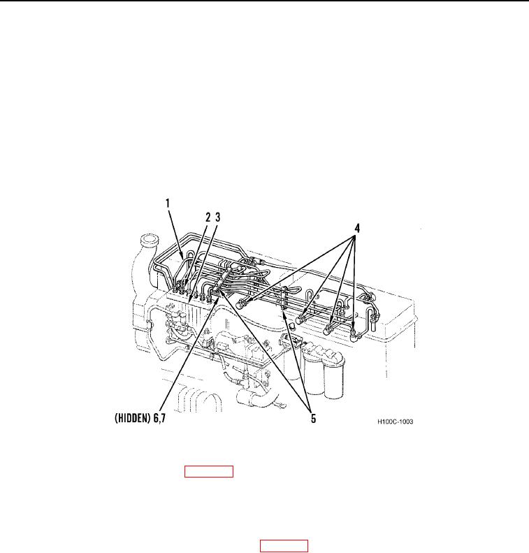
24. Install fuel lines (Figure 30, Item 2) and brackets (Figure 30, Item 5) as fuel line assembly (Figure 30, Item 1)
on fuel injection pipes (Figure 30, Item 4). Leave bracket loose until all lines are installed.
25. Install fuel injection lines (Figure 30, Item 2) on fuel injection pump (Figure 30, Item 3).
26. Install two new lockwashers (Figure 30, Item 7) and bolts (Figure 30, Item 6) on fuel line brackets (Figure 30,
Item 5).
Figure 30. Fuel Lines.
0089
27. Install turbocharger and intercooler (WP 0030).
NOTE
If they were removed, install air compressor coolant inlet hose and alternator brace on
thermostat housing and install intercooler coolant inlet hose on rear water manifold.
28. Install thermostat housing on front coolant manifold (WP 0037).
29. Install two new manifold gaskets (Figure 31, Item 2) and front coolant manifold (Figure 31, Item 1) on cylinder
head with six new lockwashers (Figure 31, Item 10) and bolts (Figure 31, Item 9).
30. Install two hose clamps (Figure 31, Item 11), coolant outlet hose (Figure 31, Item 14), and by-pass hose
(Figure 31, Item 12) on thermostat housing (Figure 31, Item 13).
31. Install two clamps (Figure 31, Item 3) and hose (Figure 31, Item 8) on front coolant manifold (Figure 31, Item 1)
and rear coolant manifold (Figure 31, Item 5).
0089-30

