
TM 5-3805-255-14
0089
INSTALLATION CONTINUED
3. In this position, adjust intake valves (as described in step 4) for cylinders 1, 2, and 4; and exhaust valves for
cylinders 1, 3, and 5.
4. Rotate crankshaft one full revolution until No. 6 cylinder is at TDC (compression). In this position, adjust intake
valves for cylinders 3, 5, and 6; and exhaust valves for cylinders 2, 4, and 6.
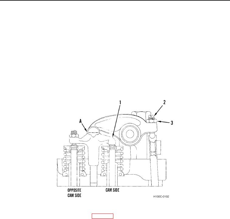
5. Loosen rocker lever nut (Figure 35, Item 3) and screw (Figure 35, Item 2).
NOTE
Feeler gauge must not be more than 0.375 in. (9.5 mm) wide to ensure a free fit between
ears of bridge.
6. Insert feeler gauge between rocker lever and valve bridge (Point A). Turn adjusting screw (Figure 35, Item 2)
until bridge (Figure 35, Item 1) just touches feeler gauge. Hold adjusting screw (Figure 35, Item 2) in position
and torque jamnut (Figure 35, Item 3) to 85 lb-ft (115 Nm).
Figure 35. Valve Lash Adjustment.
0089
7. Install two new gaskets and valve covers (WP 0027).
END OF TASK
END OF WORK PACKAGE
0089-35/(36 blank)