
TM 5-3805-255-14
0090
REMOVAL CONTINUED
Crankshaft
00090
1. Remove flywheel (WP 0026).
NOTE
It is not necessary to remove flywheel housing if replacing crankshaft rear oil seal. Refer
to WP 0088 for rear oil seal replacement.
2. Remove flywheel housing from crankcase (WP 0091).
3. Remove crankcase front cover assembly (WP 0097).
4. Remove six connecting rod bearing caps (WP 0093).
5. Push piston and rod assemblies to top of their travel.
WARNING
Use extreme caution when handling heavy parts. Provide adequate support and use
assistance during procedure. Ensure that any lifting equipment is in good condition and of
suitable load capacity. Keep clear of heavy parts supported by lifting equipment. Failure to
follow this warning may result in injury or death to personnel.
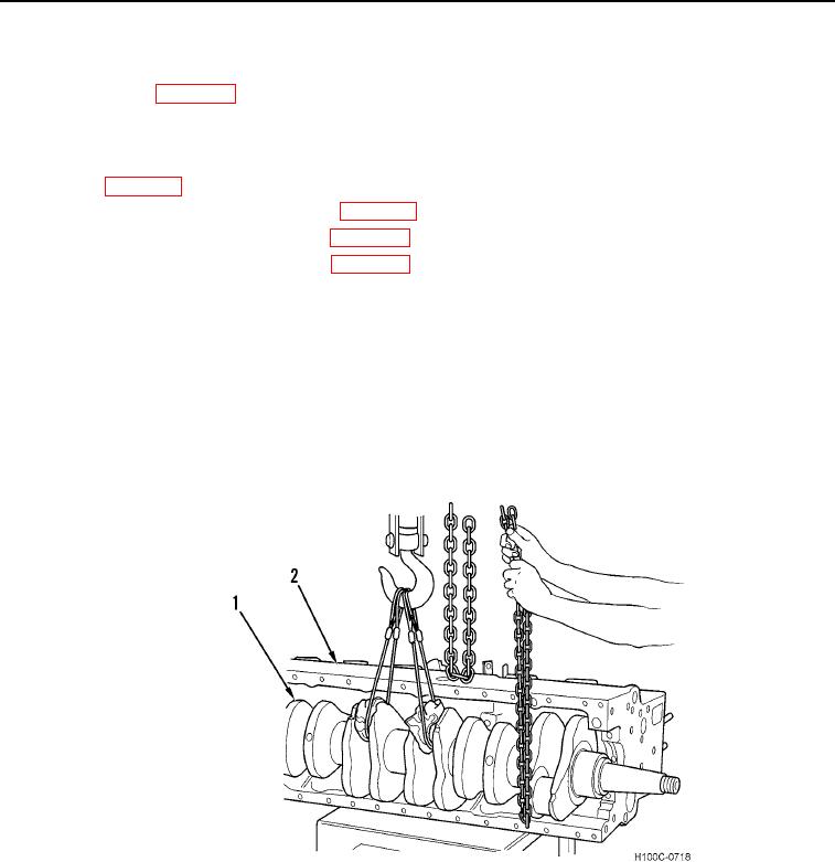
6. Use a suitable lifting device to lift crankshaft (Figure 4, Item 1) out of crankcase (Figure 4, Item 2).
Figure 4. Removing Crankshaft.
0090
0090-5