
TM 5-3805-255-14
0093
INSTALLATION CONTINUED
CAUTION
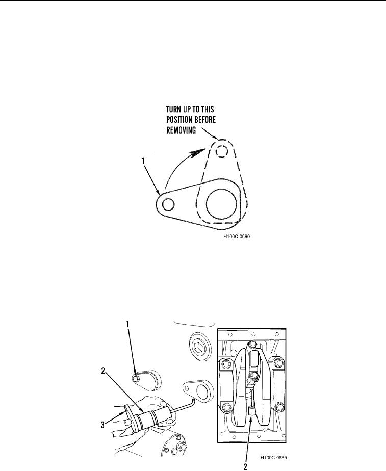
Jet cooler tubes are set at a 92 degree angle so that oil is directed to a particular spot on
underside of piston. Careful handling of this assembly is extremely important. Failure to
follow this caution may result in damage to equipment.
9. Position cooling jet (Figure 13, Item 1) at 92 degree angle as shown in Figure 13.
Figure 13. Correct Position for Installing Cooling Jet.
0093
10. Turn cooling jet (Figure 14, Item 2) 45 degrees counterclockwise so that end of flange with capscrew hole
(Figure 14, Item 3) is pointing as shown in Figure 14.
11. Install bolt (Figure 14, Item 1) through cooling jet (Figure 14, Item 2) and into engine. Tighten bolt securely.
Figure 14. Correct Position for Installing Cooling Jet.
0093
0093-14