TM 5-3805-255-14
0094
BEARING FITTING PROCEDURE CONTINUED
3. Torque two nuts to 150 lb-ft (203 Nm); then remove nuts and bearing cap. If virgin lead wire was used, use a
micrometer to measure wire which will have been crushed down to amount of clearance between crankshaft
journal and connecting rod bearing by torque applied to nuts. If plastigage was used, flattened plastic material
will be found adhering to either bearing shell or crankshaft. DO NOT REMOVE PLASTIGAGE. To determine
bearing clearance, compare width of flattened plastic material at its widest point with graduation on envelope.
Number within graduation on envelope indicates clearance in thousandths of an inch.
4. Measurement should fall between 0.0045 to 0.0075 in. (0.114 to 0.191 mm). Reinstall cap and bearing and
torque to specified amount if reading was as specified. Repeat steps 1 through 3 for all remaining connecting
rods.
5. Should reading not fall within specified limits, remove bearing from connecting rod and replace it with a new
one. However, with precision bearings used, no problem should be encountered providing crankshaft and con-
necting rod are in good order.
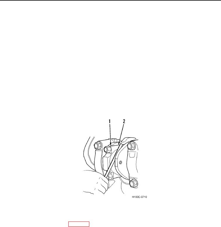
6. Check connecting rod end clearance using a feeler gauge as shown in Figure 4. Side clearance should be
between 0.0009 to 0.015 in. (0.23 to 0.38 mm). Excessive clearance may require replacement of rods or
crankshaft. Check must be made to be certain that specified end clearance exists. When checking end
clearance, feeler gauge must cover both connecting rod (Figure 4, Item 2) and cap (Figure 4, Item 1). Lack of
clearance could indicate a damaged rod or perhaps a rod bearing out of position.
Figure 4. Checking Connecting Rod End Clearance.
094
7. Install cylinder head on engine (WP 0089).
8. Install crankcase oil pan on engine.
END OF TASK
END OF WORK PACKAGE
0094-4

