
TM 5-3805-255-14
0093
CLEANING AND INSPECTION CONTINUED
00093
4. Install new bushing as follows:
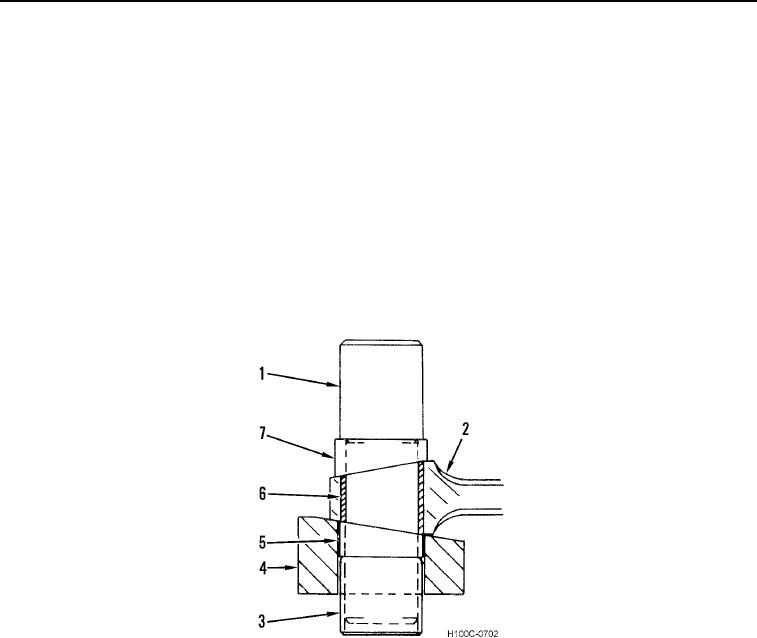
a. On mandrel (Figure 9, Item 1) assemble sleeve (Figure 9, Item 7), new piston pin bushing (Figure 9, Item
6), removing sleeve (Figure 9, Item 5) and guide sleeve (Figure 9, Item 3).
b. Place connecting rod (Figure 9, Item 2) on block (Figure 9, Item 4) in horizontal position.
c.
Assemble mandrel (Figure 9, Item 1) with all components described in step (a) into connecting rod bushing
bore. Make sure scribe mark on sleeve (Figure 9, Item 7) lines up with scribe mark on block (Figure 9, Item
4).
d. Using a suitable arbor, press bushing (Figure 9, Item 6) into bore until sleeve (Figure 9, Item 7) contacts
connecting rod (Figure 9, Item 2).
e. Check bushing (Figure 9, Item 6) to be sure bushing did not rotate during assembly.
f.
Burnish and finish ream bushing (Figure 9, Item 6) to 2.2506 to 2.2508 in. (57.166 to 57.170 mm). Break
edges of bushing bore (both sides) to 0.020 in. (0.50 mm).
Figure 9. Connecting Rod Bushing Installation.
0093
0093-10