
TM 5-3805-255-14
0098
DISASSEMBLY CONTINUED
16. With oil scavenging pump removed (if equipped), check backlash between oil pump body gear and idler gear
(Figure 6). Clearance must be 0.008 to 0.012 in. (0.20 to 0.30 mm).
17. Measure radial clearance between gears and oil pump body (Figure 7) to determine if gears or pump body
need replacement. Clearance must be between 0.0085 to 0.0100 in. (0.22 to 0.25 mm).
18. Mark oil pump body gear and idler gear in same way as scavenging pump gears, as outlined in note prior to
step 14. Remove idler gear from idler shaft.
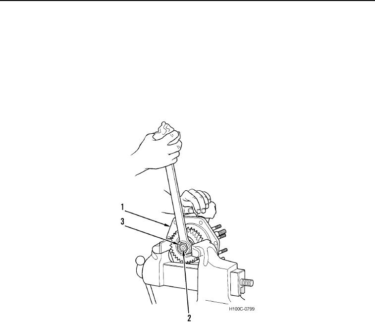
19. Reposition oil pump (Figure 10, Item 1) in vise and remove drive gear nut (Figure 10, Item 3) from drive shaft
(Figure 10, Item 2).
Figure 10. Removing Drive Gear Nut.
0098
0098-10