
TM 5-3805-255-14
0098
CLEANING AND INSPECTION CONTINUED
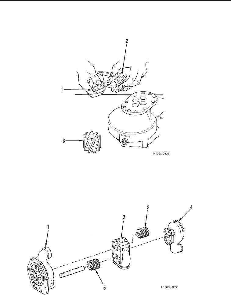
4. Using a micrometer (Figure 14, Item 1), check width of gears (Figure 14, Items 2 and 3). Allowable gear widths
are 2.623 to 2.624 in. (66.62 to 66.65 mm) for water pump body gear and idler gears, and 2.0575 to 2.0585 in.
(52.61 to 52.286 mm) for oil scavenging pump body gear and idler gear. Replace worn or damaged gears.
Figure 14. Measuring Gear Width.
0098
5. Inspect bushings in water pump housing (Figure 15, Item 4) and oil pump housing (Figure 15, Items 1 and 2)
and two bushings in oil pump idler gear (Figure 15, Item 3) for excessive wear or damage. Inside diameter of
bushings must be 0.8645 to 0.8655 in. (21.958 to 21.984 mm) for water pump housing bushing, and 0.990 to
0.991 in. (25.15 to 25.17 mm) for oil pump housing bushing. Oil pump idler gear bushing inside diameter must
be 0.8660 to 0.8670 in. (21.996 to 22.022 mm).
Figure 15. Bushing Measurement.
0098
0098-14